


Today, we are going to connect a digital depth gauge to arduino!
Source Code at GitHub:
Schematic wiring is down below.
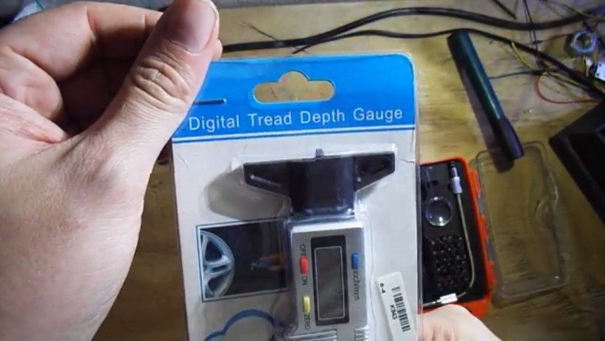
A depth gauge is a digital instrument that can measure in milimeters. in this case, we are using
a generic depth gauge, used to measure the depth of the marks in a car tire.
is a cheap way we found to measure anything, with milimetric precision !

There isn't any particular brand to choose, but they can be easily found on ebay, they cost around $4 bucks.
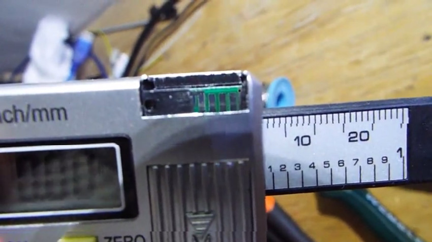
to identify if you can connect it to any electronic interface, be sure that on the top right corner, must have 4 boards pins,
that is the digital otput of the gauge.
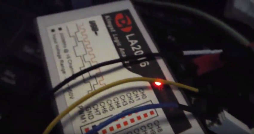
The next step, is to solder a couple of jumper cables and analyze the data output with a logic analyzer. i'm using a kingst LA2016
After a couple minutes of try and error, and searching in the net for similar experiments, mostly based on generic digital calipers, we discovered the pinout as following:
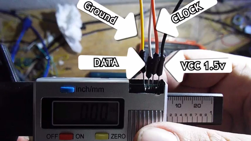
From left to right is:
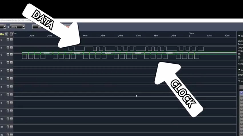
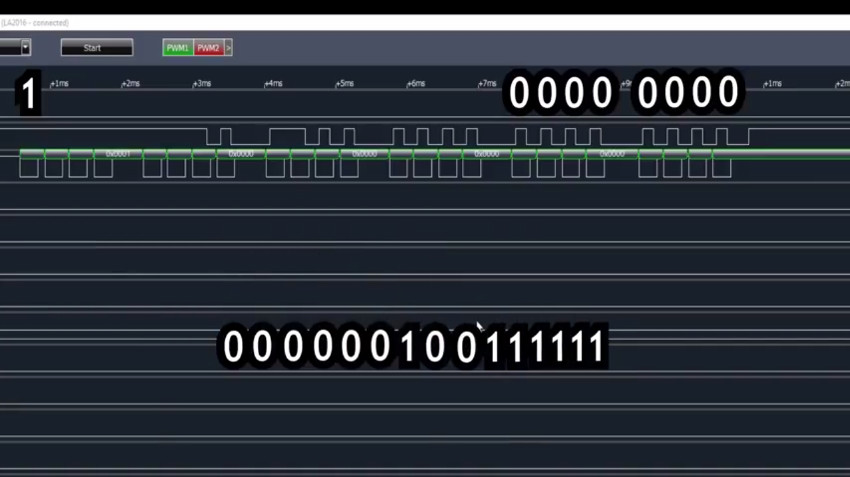
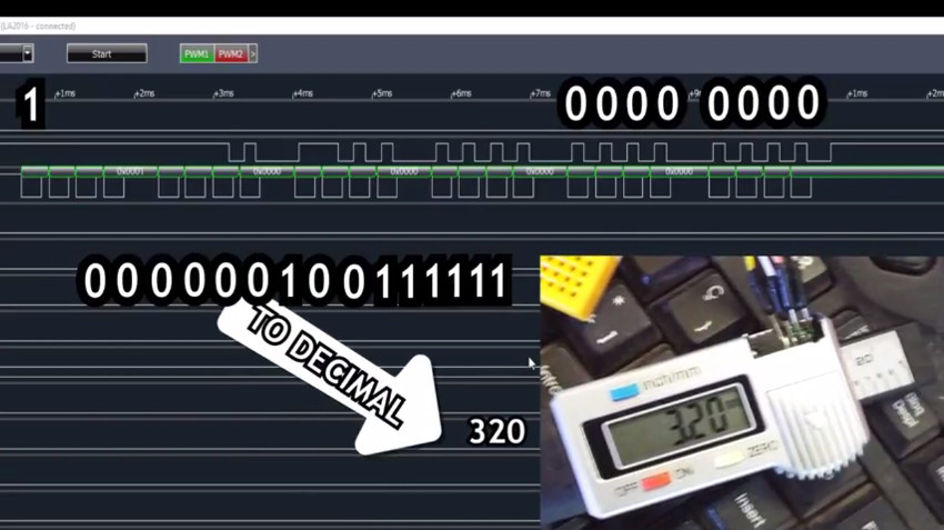
As you see, we are capturing the read of 3.20 milimeters with the logic analyzer. on this capture you will see that
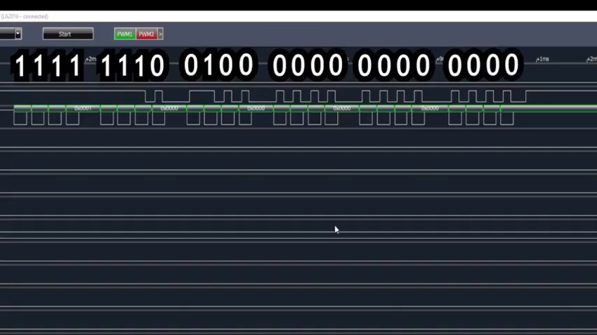
High means 1, low mean 0 and each secuence happens every 100 miliseconds and it will return a 24bits binary.
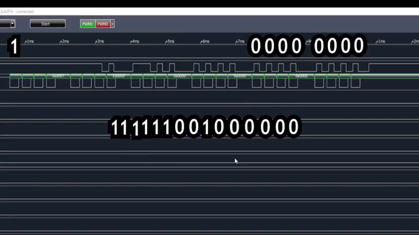
From those 24bits, the number in the screen is in the first 15bits starting from the second bit.
At the same time, for some reason, the secuence is reversed, so you must put the last bits at the beginning and viceversa
in this example, the decoding of the signals, and revert order of the values plus converted to integer, is 320, when the gauge is reading 3.20
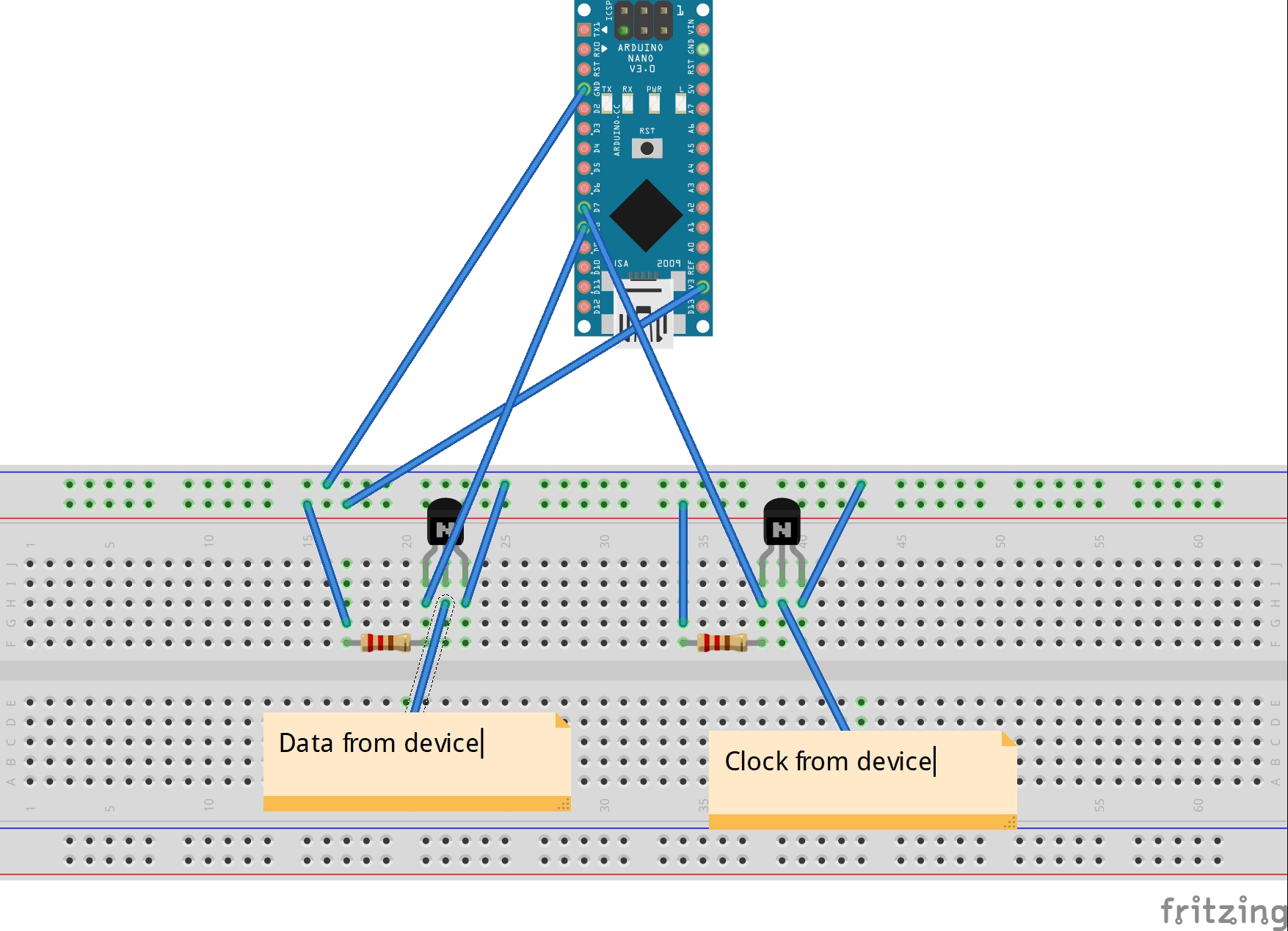 High resolution of the wiring
So, at this point we already know how the data transfer works, we need to now hook it up to the arduino.
The main problem is that the output is at 1.5v, that is not enough for the arduino to read the data, we need at least 3.3v to 5v depeding the arduino flavor we use
To overcome this, we will add 2 NPN 2N2222a transistor to amplify the signal. You can see the schematic, we are getting the voltage from the arduino, and the data plus clock
from the gauge. then back to the arduino to read the data in the amplified voltage. Plus we also add a 10K resistance in the voltage input side.
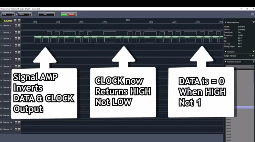
With this setup, you should be able to read the data with the minimum voltage that your arduino is capable of. using again the logic analyzer, we detect a side effect of the
signal amplifier. the signal is inverted. that means, that when originally, we read the data value when clock pin was LOW, now we need to read when is HIGH. same for the data
input, when we read a LOW, originally mean 0, now it must mean 1. like in the example, if we interpret the data as explained, we get the correct value measured.
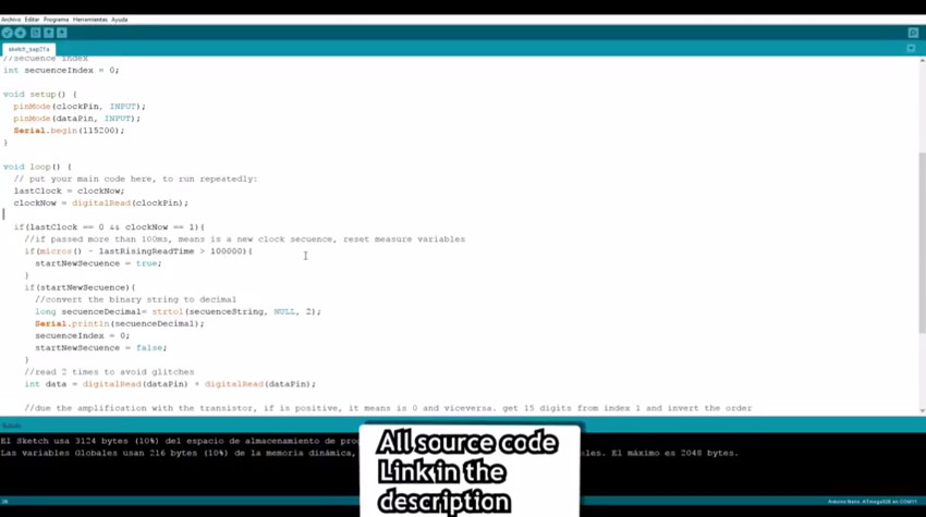
knowing exactly how the data is sent to the arduino with the signal amplifier, we are ready to write some code!.
the code is pretty simple, we just read the input from pin 7 and 8, for clock and data. we count how much time passed to know if is a new secuence or not and save the output in an array.
we take in consideration that the signal amplifier is inverting the values, and we also reverse the order of the bits in the array.
when is done, we just convert the binary to decimal with strtol.
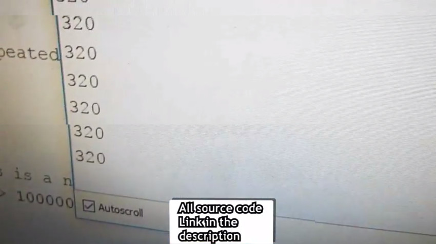
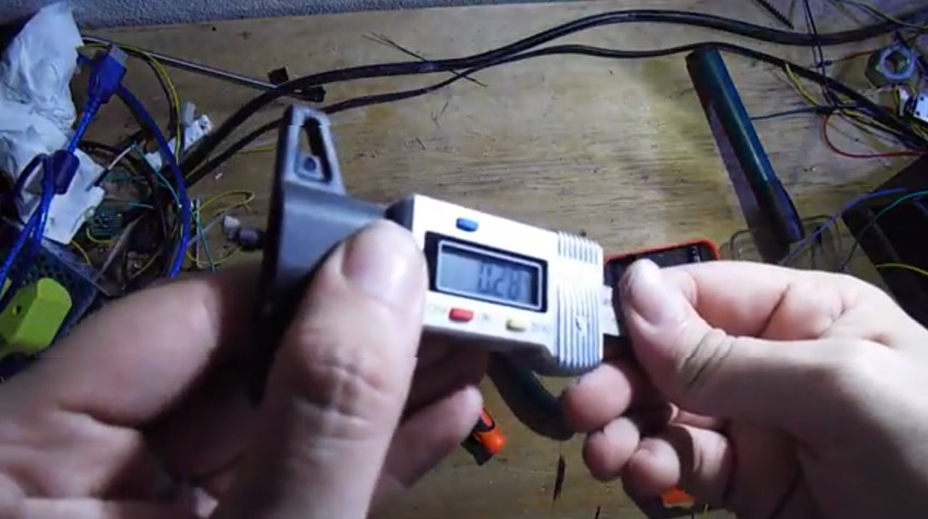
as a proof that actually works, you can see here, live, how the arduino prints the measured value to the serial console in realtime!
Remember that all source code is at GitHub:
Well, that's all for today, we hope this could be useful for your current & future projects ! see you in the next one!